
Why 22.62 degrees?

Since we introduced the Fx Track system back in 2021, we have been asked many times about why the system is structured the way it is. In particular, why do we have the R64P curve track element and why is the diverging route angle of the P40 switch 22.62º? Rather than explain these topics individually when asked, this article will attempt to describe the Fx Track system geometry and the rationale behind our choice of elements and their geometric attributes.
Design Goals
The 22.62º angle associated with the P40 switch is not an arbitrary choice; it is the result of a design process against some key goals and specifications. We knew the P40 switch was going to be a critical element in the Fx Track system. Given the scale of investment required to develop it, we had to make sure its geometry and specifications conformed to the logic and consistency of the LEGO system grid. Also, it must allow train fans to build common railway track configurations with ease and precision. The most important design goals for the P40 switch can be summarized as follows:

Given these requirements, we considered how these objectives could be achieved. In contrast to other manufacturers of track in other model train scales (e.g. O, HO, N, etc.), we face a unique and challenging constraint of aligning to a discrete grid system, that is, the LEGO system stud grid of 8 mm. Other train scales are not normally constrained to a grid and allow the freedom of organic track arrangements using elements such as flexible tracks which can be conformed to any arbitrary geometry.
Math to the Rescue!
Our design process started with first principles. We looked at the mathematical properties of the LEGO system grid and imagined how this would look when transformed by rotation. The idea was to explore the possibility of overlapping geometry which could be exploited to satisfy our design goals.
We started by analyzing a LEGO system grid rotated by 22.5º. This angle conveniently aligns to a common curve sector angle (with 4 curves per 90º) and it would be nice (but not necessary) to have a diverging angle which also matches a corresponding curve track element. Below is a diagram which shows the LEGO system grid (blue dots) and the same grid rotated by 22.5º (orange dots). Stud locations which intersect are shown with a red dot.

Also shown in this diagram are the centrelines of parallel tracks separated by 16 studs and the desired midpoint connection offset at 8 studs. Clearly there are little to no useful points of intersection; however we can see many points which are agonizingly very close! Using trigonometry, we proceeded to solve for an angle which perfectly aligned the pattern of points which seemed to intersect at periodic intervals. This angle was computed to be 22.62º (22.619864948040426º to be exact!)
The diagram below shows the LEGO system grid now rotated by 22.62º instead.

Success! A periodic system of intersecting points exist at every stud interval. We extended this analysis to find points of intersection at 8-stud and 16-stud intervals as well:

Again, we were very encouraged to find that there are guaranteed points of intersection at both 8 and 16 studs intervals. This would ensure that it was possible to build track configurations which not only yielded 16-stud parallel tracks but also align axially to the LEGO stud grid.
Incidentally, we should not be surprised that this angle does emerge in other LEGO system grid relationships. For example, it is the angle subtended across one stud interval and two bricks tall.

Finding a Special Curve
With the promising diverging route angle of 22.62º, we then had to consider which elements could be used to make a return curve from the P40 switch to make a parallel siding. We knew from previous experience with R104 track switches that a curve with a radius of 104 studs over a 22.5º sector angle was exceptionally close to matching this requirement.
In the diagram below, the coordinates of track joints along the path of a P40 switch and a return curve consisting of R104 curves is shown. Ideally, we expect the return curve to terminate at an exact LEGO stud grid interval. As expected, this does not yield an aligned track configuration. It is very close--close enough that you might be able to use this configuration if you can accept some very minor mechanical stress at the rail joints. However, our goal as a product manufacturer is to design a track system which guarantees perfect LEGO system grid alignment and avoids any intentional (yet tolerable) mechanical stress.

We know the desired return curve arrangement must traverse 22.62º in order to return the track trajectory to 0º. We also know that the maximum curvature achievable will be less than 104 studs. The possible solutions involve a myriad of combinations of straight and curve track elements. In particular, we know a custom curve track element with a 22.62º sector angle will be required.
What should this curve radius be? Ideally, it would be nice if it corresponds to one of the standard 16-stud interval radii: R40, R56, R72, R88. However, no solution for a curve element at these radii with 22.62º sector angle exists. Expanding our solution space to include straight track elements, in particular the short S8 straight element, our analysis revealed that an intermediate radius of 64 studs (in between 56 and 72 studs and on an 8 stud interval) offers a geometric solution which perfectly aligns to the LEGO system grid. The combination of an S8 straight, R64 (22.62º sector) curve, and another S8 straight forms a geometrically perfect return curve as shown in the diagram below:


Special Straights to Complete The System
We determined that a 22.62º diverging route angle was very promising and we also established a corresponding perfect return curve track solution. The next design goal was to ensure yard siding ladders could be constructed which conform to the LEGO system grid and 16-stud parallel track spacing.
Yard ladders are constructed by stacking multiple switches along the diverging path of the lead switch. Along this stack, are the straight (40 stud long) routes of each switch tilted by 22.62º. Clearly, 40 stud intervals along a 22.62º diagonal path do not align to the desired 16-stud parallel offset intervals required for each siding. Using trigonometry, we can compute that the required interval should be 41.6 studs long. That is, another 1.6 studs must be added to each switch in the yard ladder.
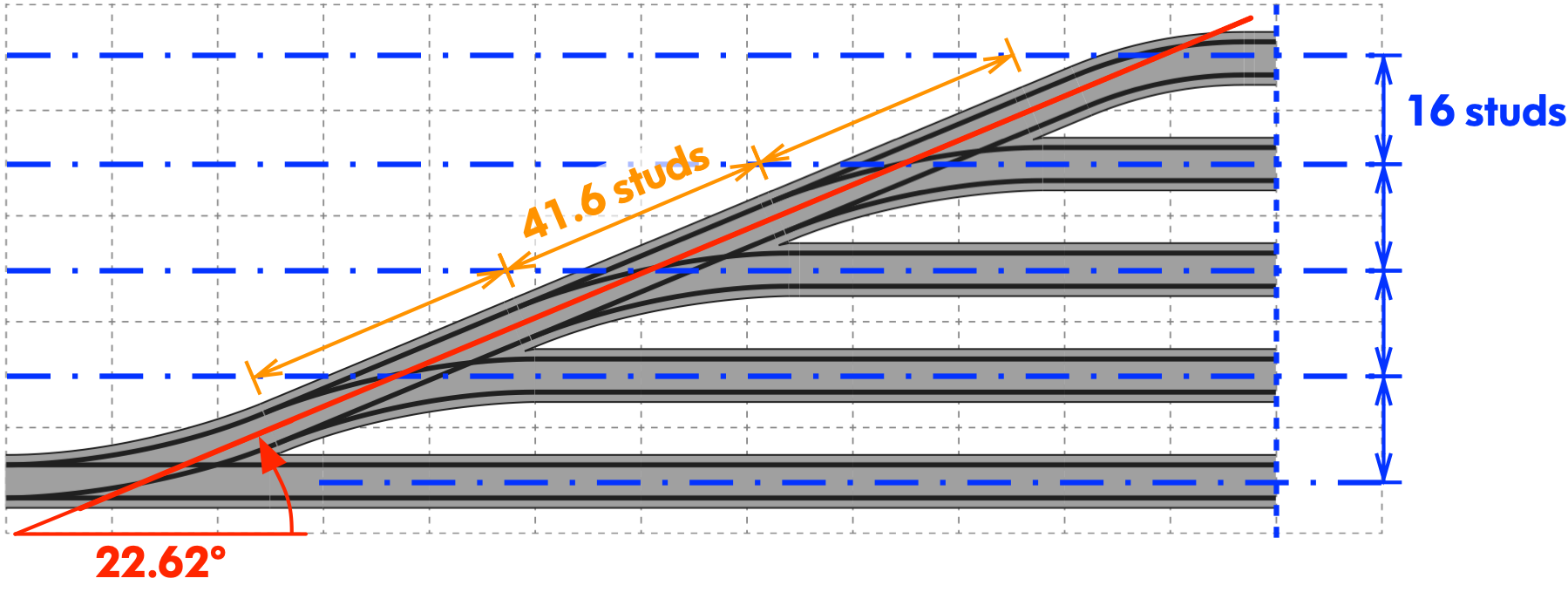
Although 1.6 studs sounds like a very awkward interval, it reassuringly fits 5x times perfectly into an 8 stud interval (5 x 1.6 = 8). This is analogous to the SNOT building ratio of 5x vertical plate intervals fitting into the same interval as two studs.
We're half way there! A 1.6-stud long straight element allows us to stack yard ladder sidings indefinitely by inserting between each P40 switch in the yard diverging path:

The next requirement is to align each siding axially (along its length) to the LEGO system grid (preferably on an 8-stud interval). As it turns out, the 1.6 stud interval which aligns P40 switches laterally can also align sidings too! In fact, a repeating pattern of 5x different multiples of 1.6-studs are used. Starting with the first siding, we add 0, 1.6, 3.2, 4.8, and 6.4 studs (repeating the sequence as required) up to the last siding. This ensures each siding is aligned to a 8-stud grid interval.

Success! We have system of geometry which satisfies our key objectives of building common and useful railway track configurations AND maintain perfect alignment with the LEGO system stud grid! However, we did want to fine tune the system slightly by introducing the S3.2 straight track. Why? Simply to reduce the awkward stack of up to 2, 3, or 4x S1.6 straights which might be required. This reduces the number of rail joints, improves appearance, and offers smoother running. (Just don't ask us to make S4.8 or S6.4 straights!)
The process for building a yard ladder of any size can easily be summarized by following procedure:

The S1.6 and S3.2 straight tracks also offer many benefits beyond making aligned yard siding ladders. They can be used to make many common parallel offset track geometries of essentially any multiple of 8-studs separation as shown in the diagrams below:


Conclusions
We hope this detailed explanation of our track system geometry gives some insight into the choice and specification of elements of the Fx Track system. Although not immediately obvious, underpinning this system is a logical and consistent system of geometry. The Fx Track system gives LEGO train fans unlimited possibilities for build amazing prototypical layouts and at the same time maintaining total compatibility with the LEGO system grid.
LEGO train layouts can be built into modular sections with clean boundaries corresponding to standard LEGO baseplates (e.g. 16x32, 32x32, 48x48). Parallel tracks will always be separated by the conventional 16-stud centreline spacing. And, if you don't want to be confined to the grid, that's ok too! The variety of Fx Track curve and straight track elements offer a vast creative landscape to construct virtually any organic and freeform train layout too!